Module 5—Wave Theory of Light
 Read
Read
Review this information by reading “The Law of Reflection” on pages 653–654 the textbook.
TR 7. Why do we measure the angle of incidence and reflection from the normal instead of the mirror’s surface? (Hint:Look at the specular reflection and diffuse reflection diagrams.)
Image Formation in Plane Mirrors
Ray diagrams, similar to those that have been used in the activities above can illustrate the process of image formation. Consider two light rays originating from the top of a tree by a smooth lake. Constructing a ray diagram that illustrates the law of reflection predicts that an image of the tree will form upside down. The dotted lines “appear” to your eyes to be rays of light from the image, but they don’t actually come from the image. Since the two light rays only appear to have originated from a single point, the image formed in this ray diagram is said to be a “virtual image.” You will learn more about this below.
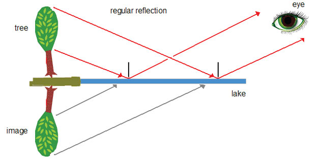
Any image formed by a plane mirror is a virtual image. Its orientation and size may be predicted by constructing a simple ray diagram based on the law of reflection.
Try This
TR 8. Complete "QuickLab 13-3: Drawing a Ray Diagram" on page 655 of the textbook. Answer questions 1, 2, 3, and 4.
TR 9. Using page 656 of the textbook, complete the following table by defining each image characteristic for plane mirrors. The definitions are found in the paragraph, not in the table. The table in the text gives you vocabulary you should use when discussing these characteristics.
Image Characteristic |
Definition |
magnification |
|
attitude |
|
position |
|
real image |
|
|
virtual image |
© Danger Jacobs /shutterstock
Image Formation for Curved Mirrors
Images formed by curved mirrors look different than those from flat mirrors. The process of image formation, however, is easily demonstrated by ray diagrams that obey the law of reflection.
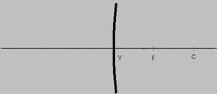
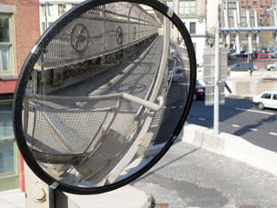
Similar to flat mirrors, the real or virtual image produced by a curved surface can be described by magnification, attitude (erect or inverted), and position. A curved mirror can be formed by cutting off a section of a spherical mirror. The inside surface would be a converging mirror. It has a concave surface that reflects rays to a central, focal point. The outside surface would be a diverging mirror. It has a convex surface that causes the reflected light to spread out. See "Figure 13.38" on page 659 in your physics textbook.
Read
Read “Image Formation in a Curved Mirror” on page 657 of the textbook.
TR 10. Using “Figure 13.36” on page 657 of the textbook as a guide, complete the following table:
Term |
Definition |
centre of curvature (C) |
|
radius of curvature (r) |
|
vertex (V) |
|
principal axis (PA) |
|
principal focal point (F) |
|
focal length (f) |
|
Ray diagrams can be used to explain and predict how an image forms in a curved mirror. Similar to that of a flat mirror ray diagram, several rays are sketched to determine the location, size, orientation, and type of image. Generally, three rays are used to follow the path of the light. Note that there are many, many rays that make the image, but only a few are required to identify its location and characteristics.
In the ray diagram below for a concave mirror, ray 1 travels parallel to the principal axis and is reflected through the mirror’s focal point. Ray 2 is incident to the mirror’s vertex. At the vertex, the surface of the mirror is perpendicular to the principal axis, so the angle of incidence and reflection are equal. Ray 3 travels through the focal point and is reflected parallel to the principal axis. These guidelines for drawing ray diagrams are summarized in the table below.
Ray Number |
Incident Ray |
Reflected Ray |
1 |
parallel to principal axis |
through F |
2 |
to vertex |
Θr = θi |
3 |
through F |
parallel to principal axis |
A real image is formed where the rays meet or converge. A virtual image is formed if the rays “appear” to have converged at some point.
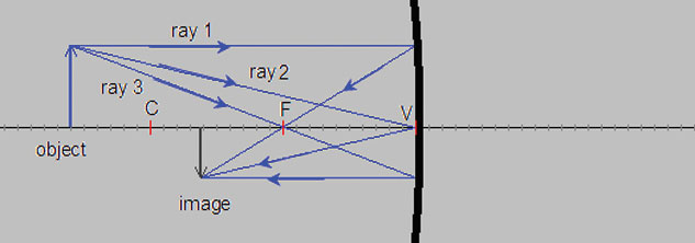
The image in this figure is real (the light rays converge at the image), inverted (upside down relative to the object), diminished in size, and located beyond the focal point.
A simulation will be used to explore the image characteristics for both concave and convex mirrors.
TR 11. Open the simulation and select “Mirror” from the dropdown menu.
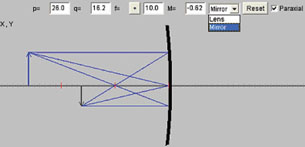
© Fu-Kwun Hwang, NTNU JAVA Virtual Physics Laboratory. Used with permission.
Click the object arrow and move it to various locations on the principal axis. Using the simulation as a guide, draw ray diagrams and describe the image characteristics when the object is located at the positions listed in Table 1 below.
Table 1: Using Ray Diagrams to Predict Image Characteristics: Converging Mirror
| Object Position | Ray Diagram |
Image Characteristics |
very far away (very left side) |
|
|
outside C |
|
|
at C |
|
|
between C and F |
|
|
at F |
|
|
inside F |
|
|


TR 12. Switch the mirror in the simulation to a diverging, convex mirror by making the focal length negative (![]() ). Complete Table 2 below. For image characteristics, record real or virtual, attitude, magnification, and position relative to mirror surface.
). Complete Table 2 below. For image characteristics, record real or virtual, attitude, magnification, and position relative to mirror surface.
Table 2: Using Ray Diagrams to Predict Image Characteristics: Diverging Mirror
| Object Position | Ray Diagram |
Image Characteristics |
very far away (very left side) |
|
|
outside C |
|
|
at C |
|
|
between C and F |
|
|
at F |
|
|
inside F |
|
|